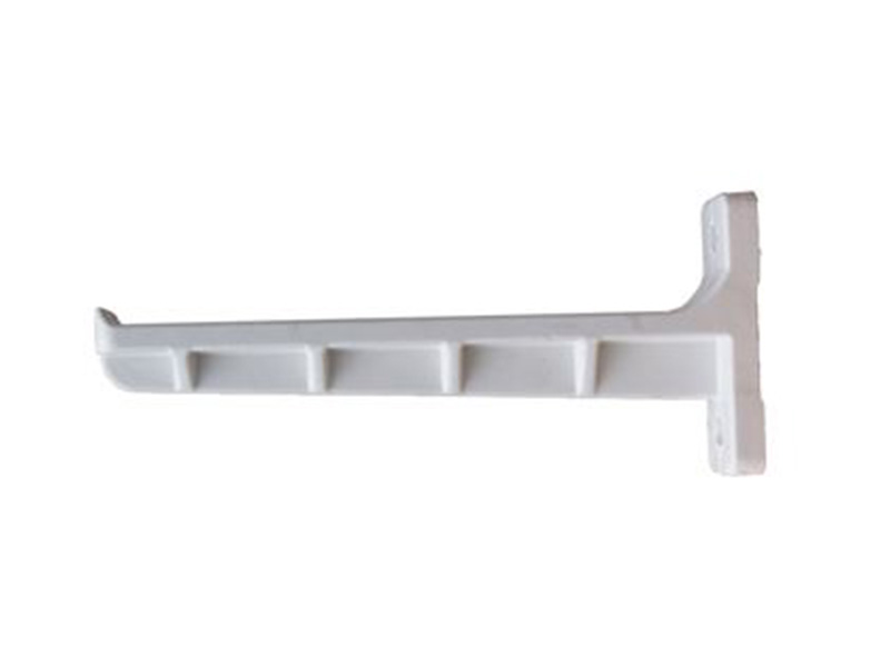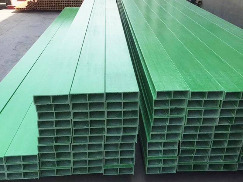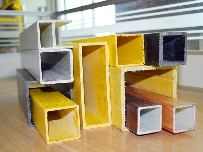
Floor-beam selection is usually governed by the way people and supported grating experience movement, not by an isolated ultimate-strength number. Project teams researching FRP floor beam usually need a selection or execution method, not another list of generic FRP benefits. The guide therefore aims to help platform designers size FRP floor beams from tributary loads, deflection and grating interfaces.
Each section answers a decision created by the H1, beginning with “Calculate Tributary Width and Load Cases.” Project calculations, local rules and the responsible professional’s review still govern the final solution.
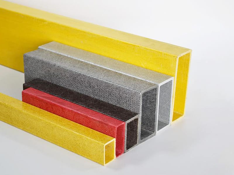
Calculate Tributary Width and Load Cases
Map which area delivers load to each beam and separate uniform, concentrated, equipment and maintenance cases. Check edge and opening beams independently. Assign responsibility for “Calculate Tributary Width and Load Cases” in the project scope instead of leaving the interface between trades undefined.
Use Actual Clear Span and Support Condition
Measure between bearing points and state continuity assumptions. A nominal bay dimension can overstate or understate the structural span. Use “Use Actual Clear Span and Support Condition” as a documented hold point when later work would conceal the condition or make correction difficult.
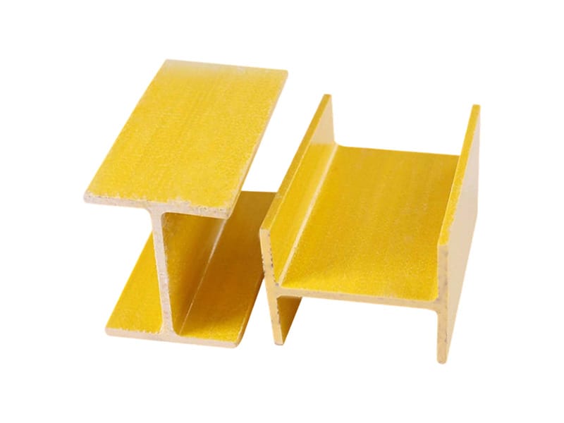
Set Deflection and Vibration Criteria
Choose serviceability limits for walking comfort, grating alignment and supported equipment. Review rhythmic or rotating loads where relevant. Link the FRP floor beam decision on “Set Deflection and Vibration Criteria” to the relevant dimension, calculation assumption or inspection record.
Coordinate Beam Spacing With Grating Direction
Place supports to suit grating bearing bars, panel seams and openings. Avoid secondary framing that leaves narrow unsupported panel strips. For this topic, make “Coordinate Beam Spacing With Grating Direction” a checked item on the drawing or schedule before fabrication.
FRP Floor Beam decision table
| Project decision | Evidence to request | Risk if unresolved |
|---|---|---|
| Calculate Tributary Width and Load Cases | Map which area delivers load to each beam and separate uniform, concentrated, equipment… | supplier proposals based on incompatible scope assumptions |
| Use Actual Clear Span and Support Condition | Measure between bearing points and state continuity assumptions | a decision that cannot be traced back to the recorded site condition |
| Set Deflection and Vibration Criteria | Choose serviceability limits for walking comfort, grating alignment and supported equipment | one trade solving its own issue by creating a conflict for another |
| Coordinate Beam Spacing With Grating Direction | Place supports to suit grating bearing bars, panel seams and openings | a small detailing error repeated across every unit |
Provide Lateral Restraint to Beam Flanges
Show cross members, decking or bracing that prevents twist. Confirm restraint during erection as well as in the completed platform. The project review should close “Provide Lateral Restraint to Beam Flanges” with measurable acceptance information rather than a general supplier statement.

Frame Openings Without Unreviewed Notches
Use headers and trimmers around equipment and stairs. Keep pipe or cable penetrations out of beam webs and flanges unless specifically approved. Record how the selected system addresses “Frame Openings Without Unreviewed Notches” so site changes can be compared with the approved basis.
Detail Connections for Reactions and Access
Provide bearing, bolts, plates and edge distances for actual end reactions. Check that installers can reach both sides where the detail requires it. Assign responsibility for “Detail Connections for Reactions and Access” in the project scope instead of leaving the interface between trades undefined.
Issue a Coordinated Beam and Grating Schedule
List section, span, orientation, elevation, connection family and supported panel type. Align member marks across plans, sections and fabrication drawings. Use “Issue a Coordinated Beam and Grating Schedule” as a documented hold point when later work would conceal the condition or make correction difficult.
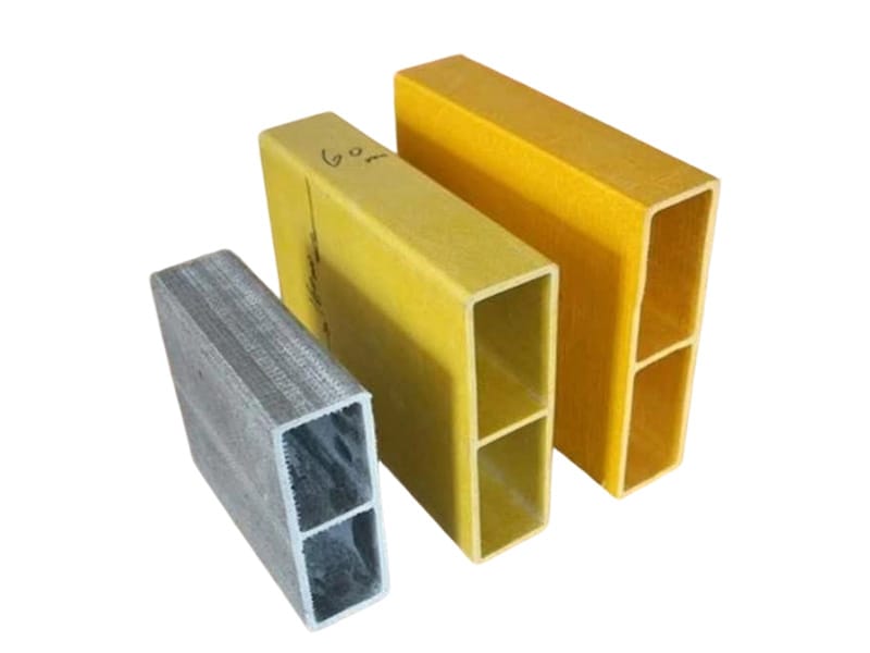
Documenting FRP Floor Beam decisions
A procurement package for FRP floor beam should make the design basis behind “Issue a Coordinated Beam and Grating Schedule” reviewable. The exact submittals depend on scope, but the owner should be able to identify what was selected, why it was selected and how the installed work was accepted. Avoid asking for unrelated certificates simply to make the package look complete.
- A dimensioned layout showing the orientation and interfaces of FRP floor beam.
- The stated loads, exposure conditions and operating assumptions used for FRP floor beam.
- Product data and material descriptions that correspond to the offered configuration.
- Connection, foundation, support or installation details within the supplier’s scope.
- Inspection, test, handling and maintenance information relevant to the finished work.
FRP Floor Beam: standards and design responsibility
Requirements for “Use Actual Clear Span and Support Condition” vary by location, facility and duty. A project review may draw on ASCE structural standards, ASTM D3917, ASTM D638 and OSHA walking-working surfaces. These links provide authoritative starting points; the responsible professional must decide what applies to FRP floor beam and use the current edition required by the project.
Five practical questions about FRP floor beam
Why should a team address calculate tributary width and load cases for FRP floor beam?
Map which area delivers load to each beam and separate uniform, concentrated, equipment and maintenance cases. Check edge and opening beams independently. In a FRP floor beam project, the answer should be recorded in a drawing, calculation, approved submittal or inspection note appropriate to the decision. If the necessary site information is unavailable, state the assumption and identify who must close it before work proceeds.
How should a designer address use actual clear span and support condition for FRP floor beam?
Measure between bearing points and state continuity assumptions. A nominal bay dimension can overstate or understate the structural span. In a FRP floor beam project, the answer should be recorded in a drawing, calculation, approved submittal or inspection note appropriate to the decision. If the necessary site information is unavailable, state the assumption and identify who must close it before work proceeds.
When should a contractor address set deflection and vibration criteria for FRP floor beam?
Choose serviceability limits for walking comfort, grating alignment and supported equipment. Review rhythmic or rotating loads where relevant. In a FRP floor beam project, the answer should be recorded in a drawing, calculation, approved submittal or inspection note appropriate to the decision. If the necessary site information is unavailable, state the assumption and identify who must close it before work proceeds.
What evidence helps a buyer address coordinate beam spacing with grating direction for FRP floor beam?
Place supports to suit grating bearing bars, panel seams and openings. Avoid secondary framing that leaves narrow unsupported panel strips. In a FRP floor beam project, the answer should be recorded in a drawing, calculation, approved submittal or inspection note appropriate to the decision. If the necessary site information is unavailable, state the assumption and identify who must close it before work proceeds.
How can an owner address provide lateral restraint to beam flanges for FRP floor beam?
Show cross members, decking or bracing that prevents twist. Confirm restraint during erection as well as in the completed platform. In a FRP floor beam project, the answer should be recorded in a drawing, calculation, approved submittal or inspection note appropriate to the decision. If the necessary site information is unavailable, state the assumption and identify who must close it before work proceeds.
FRP Floor Beam decision record and handover
A strong FRP floor beam article should connect “Calculate Tributary Width and Load Cases” to a better project brief, and a strong project brief should lead to evidence. Record the selected configuration, controlling loads or operating conditions, exposure, interfaces, installation limits and acceptance checks. That record is more valuable than a broad claim that one material or product is suitable for every site.
Review the FRP Floor Beam product information, browse the FRP product range, compare this topic with the related guide FRP H Profile Selection for Industrial Framing, and read why FRP is used in demanding environments. To discuss drawings or service conditions for FRP floor beam, contact the XPFRP project team.