Table of Contents
Table of Contents
FRP I beam is usually considered when a project needs dependable service in wet, corrosive, electrically sensitive, or maintenance-intensive conditions. The material choice alone does not determine whether the installation will perform as intended. Project teams must connect site conditions, loads, geometry, access, fabrication, and inspection requirements before requesting a quotation.
This guide explains how engineers and project procurement teams can specify FRP I beam for platform framing, equipment supports, and chemical plant structures. It focuses on practical decisions that can be confirmed on drawings, data sheets, supplier submittals, installation plans, and inspection records. It does not replace calculations by the responsible engineer or the requirements of the authority having jurisdiction.
A useful enquiry for FRP I beam should describe the operating environment and the required function before listing dimensions. That sequence helps suppliers identify missing information and prevents a profile, panel, enclosure, or assembly from being selected only because its nominal size appears familiar.
Define the Job of FRP I beam
Begin with a short design statement. Identify who will use or maintain the installation, what it must support or separate, how often it will be accessed, and what failure would interrupt operations. For FRP I beam, the service description should distinguish normal operation from temporary construction, cleaning, shutdown, or emergency conditions.
Record the physical boundaries of the work. Existing structures, equipment nozzles, doors, platforms, cable routes, drainage paths, vehicle envelopes, and future expansion can all affect the available geometry. A supplier can respond more accurately when the enquiry includes a marked-up plan and several controlling dimensions rather than a single overall length.
Survey the Site and Exposure Conditions
Site exposure should be described with operating language instead of broad labels such as “corrosive.” Note persistent moisture, splash, immersion, salt-laden air, ultraviolet exposure, washdown chemicals, fumes, abrasive solids, temperature cycles, and the likelihood of accidental impact. The suitable resin, surface veil, color, and hardware strategy for FRP I beam depend on this combination.
Where chemicals are present, provide names, concentrations, temperatures, contact duration, and whether chemicals may be mixed. Compatibility should be confirmed for the actual service. A general corrosion-resistance statement is not a substitute for reviewing the expected exposure and the cut edges, drilled holes, joints, and fasteners that may experience different conditions from the main surface.
Establish Loads and Performance Criteria
The responsible designer should define dead, live, maintenance, wind, snow, impact, thermal, hydrostatic, operating, and accidental loads that are relevant to the project. The list will vary, but the important point is that FRP I beam cannot be selected from material strength alone. Span, support condition, load direction, duration, and allowable movement are equally important.
Deflection frequently controls serviceability before ultimate strength controls capacity. Excess movement can disturb seals, loosen connections, affect walking comfort, change clearances, or make doors and removable panels difficult to operate. State both strength and serviceability criteria, and identify any vibration, fatigue, or repeated load that requires separate consideration.
Choose Geometry and Configuration
Translate the functional requirements into a coordinated layout. For FRP I beam, review design loads, span, lateral restraint, deflection, and connection zones. Show critical sections, supports, openings, interfaces, and access zones. If dimensions remain provisional, identify them as such so the supplier does not treat an early layout as approved fabrication information.
Avoid changing one dimension without checking its effect on the whole assembly. A deeper section, closer post spacing, wider panel, larger opening, or different support interval may change weight, connection forces, fabrication access, drainage, and installation sequence. Geometry should be resolved together with loads and connections.
Plan Connections and Interfaces Early
Connections often determine whether FRP I beam can be installed without field rework. Identify the supporting material, edge distances, bolt access, bearing surfaces, anchor type, isolation requirements, and allowable field drilling. Loads should transfer through defined paths rather than through unsupported edges or local details that were never checked.
Coordinate interfaces with concrete, steel, masonry, piping, equipment, and other FRP components. Holes and cutouts should be located away from highly stressed regions where practical. Where field cutting is unavoidable, require appropriate tools, dust control, edge treatment, and inspection so the completed detail remains consistent with the design intent.

Address Safety, Access, and Maintainability
Safety requirements apply to the complete installation, not only to the material. Review walking surfaces, fall hazards, electrical clearances, restricted access, manual handling, confined-space implications, lifting points, sharp edges, and emergency routes as relevant. The design of FRP I beam should be coordinated with site procedures and applicable regulations.
Maintenance access deserves the same attention as initial installation. Determine how components will be cleaned, inspected, removed, or replaced. Provide room for tools and fasteners, and avoid details that trap water or debris. A maintainable layout makes inspection evidence easier to collect and reduces the temptation to use unsafe shortcuts later.
Compare FRP I beam With Practical Alternatives
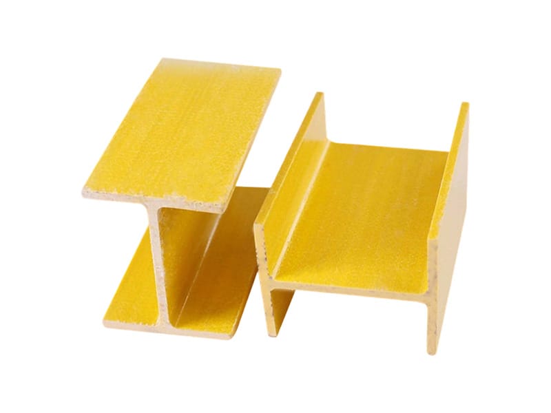
Compare FRP I beam with H beams, channels, and steel beams using the actual project conditions. The purpose is not to declare one material universally superior. The better option is the one that meets the defined loads, environmental exposure, installation constraints, maintenance approach, and documentation requirements with acceptable project risk.
| Decision area | What to verify | Why it matters |
|---|---|---|
| Environment | Chemical, moisture, UV, temperature, and electrical exposure | Guides material and protection choices |
| Structure | Loads, span, restraint, deflection, and interfaces | Confirms serviceability and load paths |
| Installation | Access, lifting, cutting, anchors, and tolerances | Reduces field changes and delays |
| Maintenance | Cleaning, inspection, replacement, and records | Supports reliable long-term operation |
Prepare a Complete Supplier Enquiry
A clear request for quotation should include drawings, quantities, service conditions, design loads, dimensional tolerances, color, surface requirements, connection scope, testing or inspection expectations, documentation, packing, and delivery constraints. State which party is responsible for calculations, detailed design, anchors, and installation. This prevents assumptions from becoming hidden scope gaps.
- Describe the operating function and exposure for FRP I beam.
- Attach plans, elevations, sections, and interface dimensions.
- List design loads, allowable deflection, and applicable project standards.
- Identify resin, surface, color, fire-performance, and electrical requirements that are genuinely project-specific.
- Define submittals, inspection points, packing, labeling, and installation responsibilities.
Review Drawings and Documentation Before Fabrication
Supplier drawings for FRP I beam should be checked against the project model and the latest civil, structural, mechanical, and electrical information. Review dimensions, member orientation, panel joints, supports, gates or openings, penetrations, hardware, labels, and installation notes. Comments should identify a required change rather than simply marking an item as “noted.”
Request documentation that can be verified and used by the project team. Appropriate submittals may include product data, material descriptions, dimensional information, calculation assumptions, fabrication drawings, inspection records, handling instructions, and maintenance guidance. Do not request certifications or test reports that are unrelated to the actual specification.
Avoid Common Specification Mistakes
Common mistakes include copying dimensions from a steel detail, specifying only a generic resin name, ignoring deflection, omitting support conditions, leaving anchors undefined, and waiting until installation to coordinate penetrations. Another frequent problem is asking the supplier to “meet all standards” without identifying the project location, use, or governing requirements.
Treat FRP I beam as an engineered part of a system. A complete design connects material properties to geometry, support, connection, environment, installation, and inspection. When one of those elements is missing, the project team should resolve it before approving fabrication.
Installation and Handover Checklist
Before installation, verify delivered quantities, identification, visible condition, dimensions, and storage arrangements. Confirm that supporting work is complete and within tolerance. During installation, protect components from uncontrolled impact, use approved lifting points, follow the connection details, and record any field modification for engineering review.
At handover, inspect FRP I beam for alignment, support, fastener completion, treated cut edges, damage, clearances, access, and cleanliness. Provide the owner with approved drawings, product information, inspection records, and a practical maintenance schedule. Photographs linked to drawing locations can make future condition reviews more useful.
Authoritative References to Check
Project requirements vary by location and use. The design team should consult the current editions of relevant sources, including ASCE structural standards, ASTM D3917, ASTM D638, and OSHA walking-working surfaces. These references help frame the review, but the responsible professional must determine which provisions apply.
Frequently Asked Questions
What information is needed to quote FRP I beam?
Provide application, quantities, drawings, dimensions, loads, support conditions, exposure, connection scope, required documentation, and delivery constraints. A supplier can then identify questions before pricing and fabrication.
Can FRP I beam replace a steel detail directly?
Not automatically. Material stiffness, section behavior, connection details, tolerances, and failure modes differ. The responsible designer should check the complete load path and serviceability requirements.
How should chemical resistance be specified for FRP I beam?
List chemicals, concentrations, temperatures, contact duration, cleaning agents, and exposure type. Ask the supplier to review compatibility for the proposed resin and the fabricated details.
Can FRP I beam be cut or drilled on site?
Field fabrication may be possible when it is permitted by the approved drawings and performed with appropriate tools, dust control, edge treatment, and inspection. Unreviewed changes should be avoided.
How often should FRP I beam be inspected?
Set the interval from exposure, consequence of failure, operating experience, and site rules. Inspect after impact, abnormal loading, chemical release, fire exposure, or significant modification.
Final Specification Review
- Confirm that FRP I beam dimensions match the latest coordinated drawings.
- Check that FRP I beam loads and support assumptions are stated clearly.
- Verify that FRP I beam materials suit the documented service environment.
- Coordinate FRP I beam connections, access, and installation responsibilities.
- Include FRP I beam inspection and handover records in the project file.
Conclusion
A successful FRP I beam specification starts with service conditions and ends with coordinated fabrication, installation, and inspection information. Define the function, loads, environment, geometry, interfaces, safety needs, and documentation before comparing proposals. This approach supports clearer supplier communication and a more predictable project outcome.
Review the related FRP I Beam product page, learn more about Why FRP, browse the FRP product range, and read the FRP pultruded profiles guide. For a project-specific discussion, contact the XPFRP team with drawings and service conditions.